Introduction to the UVM
When I was getting into UVM (Universal Verification Methodology) as my verification framework or methodology, I faced many difficulties. So I decided to make an article for beginners or intermediate people who do not have a clear picture of the UVM.
I am not going to explain the history of UVM here. Because intermediate people are more like to know the theories other than the history lesson. But note that there is a history of evolution of UVM. Let’s start with the “what” and “why.”
The UVM frame work provides features to you to make a layered and object-oriented testbench. It mainly focuses on the “separation of concern” among the various team members. It means DV engineers can easily work on separate UVM components, which work as separate entities. That is the main purpose of the UVM. If you do a verification test bench correctly, other DV engineers can easily understand and easily work with your testbench. Also, it will provide the reusability of your testbench. As an example, if you have made a uvm testbench for the I2C protocol, it can be used for any verification test that needs to verify using I2C.
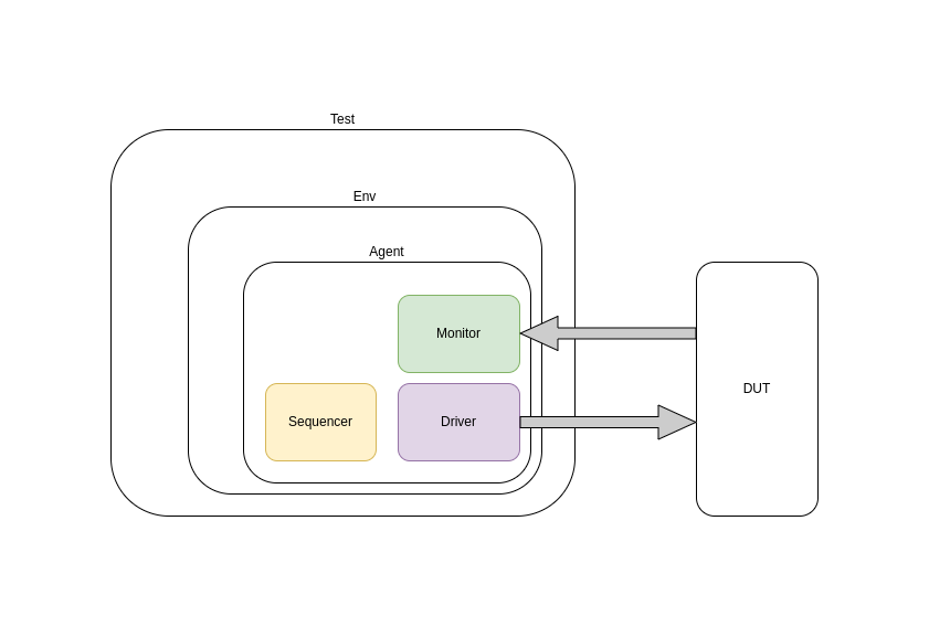
When we consider UVM, the main part is UVM components and UVM objects. UVM components are one of the main elements, which represents hierarchy; also, UVM components act like “static” members. Examples of UVM components are Test, Env, Agent, Monitor, Driver, etc. UVM objects are dynamically created objects, like uvm_sequence_item, uvm_sequence, etc. Do not worry about these names; I will explain those components and objects one by one. The following diagram shows the hierarchical connection of a UVM testbench.
When you make an architectural testbench you will need some design patterns like factory methods, phasing, etc. But I will come up with those design patterns later. Because understanding UVM components and objects is the most important and fundamental approach for DV engineers.
There are two different levels. Those are transaction-level and pin-level. When you do RTL design, you consider it pin-level. But when you are doing UVM testbench, you should treat it as software, and then this level we called the transaction level. Those transaction-level communication and pin-level communication happen via virtual interface.
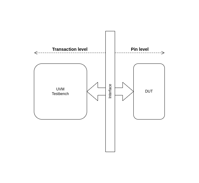 (Note: Please forget the mindset of signals of RTL when you are developing the UVM testbench. Most of the students do not understand this situation.)
Now you know what the transaction level is and what the pin level is.. As a diagram, there are several UVM components and objects (SystemVerilog base classes). I will start with UVM objects.
uvm_seq_item: This is the atom of the UVM testbench. because many people, including me, are getting wrong about this UVM_seq_item. Don’t be confused. When we are driving stimulus from driver to pins of DUT, we are sending that stimulus as uvm_seq_item to driver. that uvm_seq_item contains the necessary information for converting transaction level data to pin level data, and it should contain necessary data and methods for verification testbench.
class uart_seq_item extends uvm_sequence_item;
`uvm_object_utils(uart_seq_item)
local rand bit [7:0] character;
local rand bit parity;
function new(string name="uart_seq_item");
super.new(name);
`uvm_info("[SEQ_ITEM]","constructor",UVM_HIGH)
endfunction: new
//set data values
function void set_data(
bit [7:0] character,
bit parity_en,
bit parity
);
this.character = character;
this.parity_en = parity_en;
this.parity = parity;
endfunction: set_data
//get data value
function void get_data(
output bit [7:0] character_out
);
character_out = this.character_mask & this.character;
endfunction: get_data
//get parity value
function void get_parity(
output bit parity_out
);
parity_out = this.parity;
endfunction: get_parity
function void do_print(uvm_printer printer);
printer.m_string = convert2string();
endfunction: do_print
endclass : uart_seq_item
This is a simple example of a UART sequence item. The next important concept is phasing.
Phasing
Phasing is an architecture for the execution flow of a testbench. There are groups of phases in UVM. that are executed in the following order.
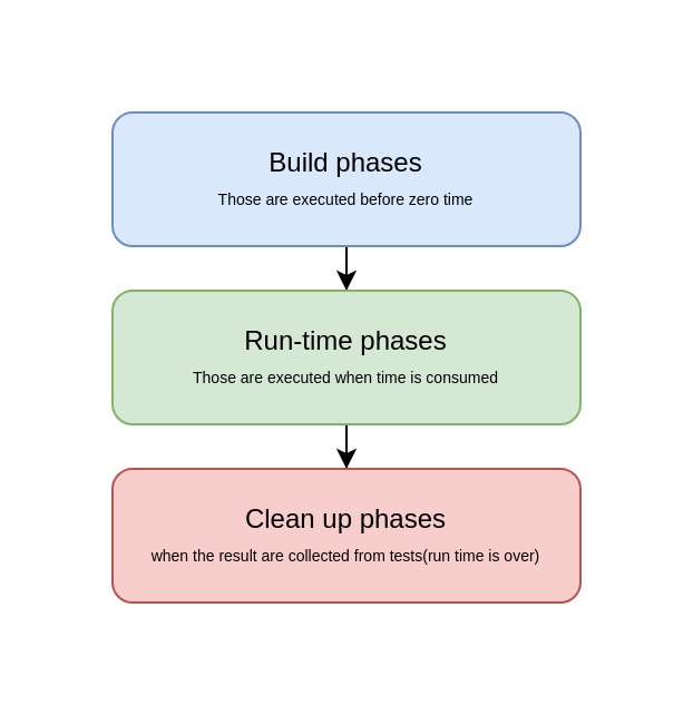
You can use only 3 main phases for a simple testbench.
function void build_phase(uvm_phase phase);
// executions before starting the simulation
endfunction
task run_phase(uvm_phase phase);
// while simulation is running (time consuming)
endtask
function void report_phase(uvm_phase phase);
// After the simulation is done
endfunction
But don’t forget!. There are many phases that the advanced uvm_testbench might need. I will describe those in another article.
UVM components are the main body of the testbench. Examples of the pre-built UVM_components are UVM_driver, UVM_monitor, UVM_agent, UVM_subscriber, UVM_env, and UVM_test. Those are useful when you are using a reusable, readable UVM testbench. Because it has “separate of concern” for each component. Following shows the skeletons of UVM components.
class agent extends uvm_agent;
`uvm_component_util(agent)
//agent code here
endclass
class driver extends uvm_driver #(seq_item);
`uvm_component_util(driver)
//driver code
endclass
class monitor extends uvm_monitor;
`uvm_component_util(monitor)
//driver code
endclass
class env extends uvm_env;
`uvm_component_util(env)
//driver code
endclass
class test extends uvm_test;
`uvm_component_util(test)
//driver code
endclass
This article is only for getting a rough idea about the building blocks of the UVM test. I will explain the whole UVM architecture with a simple example later. I guess you have gotten an idea about UVM.